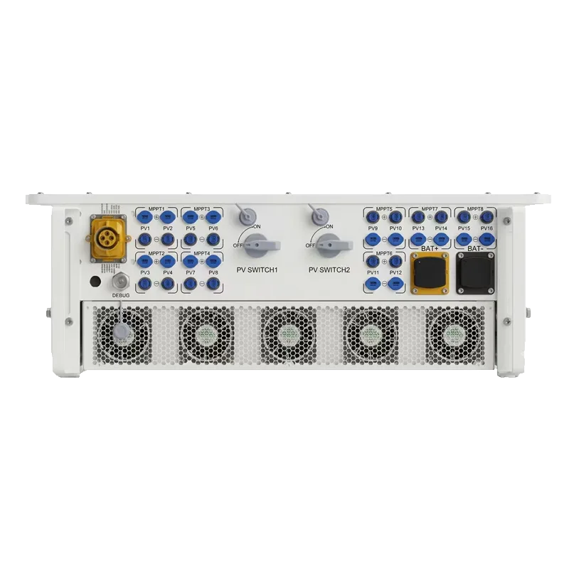


European-standard PCS to US-standard voltage: N conductor return
Summary: Drawing on a Mexican solar-plus-storage project case, this analyzes the missing N conductor return path caused by single-phase loads when a European-standard 400 V PCS is stepped to US-standard voltage via a transformer, along with corrective approaches.
Introduction: A Misread Technical Issue
A solar-plus-storage project in Mexico offers a case worth reviewing: a system using a European-standard 400 V PCS (Power Conversion System) stepped through a transformer to a US-standard voltage regime showed abnormal phase voltage sampling on the PCS side during operation, and was at one point misdiagnosed as a "product quality problem." Investigation showed the root cause was not the PCS itself, but that the system design stage had not adequately accounted for the dependence of single-phase loads on the N conductor (neutral) return path. This article works from electrical principles to lay out the cause, symptoms and corrective path for reference by system integrators.
Background: Voltage Regime Differences in Mexico
Mexico belongs to the North American market system, where common voltage regimes are 120/240 V single-phase and 480 V three-phase; many imported PCS units, however, are designed to the European 230/400 V three-phase four-wire system. Integrators typically add a transformer at the PCS output to perform the voltage conversion, but easily overlook one key point: the continuity of the N conductor return path directly determines whether single-phase loads can operate normally and whether the PCS can obtain an accurate voltage reference.
In-Depth Analysis of the Problem
1. Root Cause
In this case, single-phase equipment such as meters and air conditioners was installed in the system cabinet, and these devices draw phase voltage between the phase conductor and the N conductor. The design flaw was that the N conductor on the PCS side did not form a complete return path, so when single-phase loads were energized, the PCS could not detect complete phase voltage sampling.
2. Specific Symptoms
- PCS phase voltage sampling values were unstable, with severe imbalance between phase voltages;
- Some precision single-phase equipment reset frequently or operated abnormally;
- The system triggered overvoltage/undervoltage protection and disconnected from the grid frequently.
3. Technical Principle
In a three-phase four-wire system, the N conductor carries the return current of single-phase loads. The current path of a single-phase load is: phase conductor → load → N conductor. If the N conductor return path on the PCS side is incomplete, this leads to:
- Interruption of the current path, so single-phase loads cannot operate normally;
- Loss of an accurate voltage reference point for the PCS sampling circuit;
- Drift of the system ground potential, affecting the overall voltage reference.
From the standpoint of symmetrical components, a single-phase load introduces a zero-sequence component into the system, and the zero-sequence current requires a path through the N conductor. When the N conductor is missing or has high impedance, the zero-sequence current is forced to return through the PE conductor or the earth, the neutral point potential shifts accordingly, and phase voltage sampling is naturally distorted. This mechanism is consistent with the IEC 60364 requirement to separate the earthing and protective conductor functions in a TN system, and is also relevant to the EN 50549 requirements for voltage monitoring of grid-connected converters.
Solutions and Preventive Measures
1. Correct System Design
- Continuous N conductor throughout: from the PCS output to the transformer and on to the load distribution panel, the N conductor should remain continuous, avoiding open circuits or high-impedance connections.
- Transformer selection and wiring: choose a dedicated transformer suited to European-to-US standard conversion, confirm the winding connection arrangement (such as Δ-Y) and provide a complete N conductor tap point.
2. On-Site Troubleshooting and Correction
- Continuity testing: check the continuity of the N conductor from the PCS to the transformer section, ensuring resistance is less than 0.5 Ω.
- Earthing system check: confirm that the correct TN-S earthing method is used, with the N conductor and PE conductor connected only once, at the transformer neutral point.
- Voltage monitoring: measure the PCS-end voltages of each phase (phase-to-phase and phase-to-N) under different load operating states and record the data to analyze abnormal patterns.
3. System Integration Recommendations
- Design stage: complete the single-line diagram design with the N conductor path clearly marked; calculate the N conductor current according to the maximum unbalanced load to ensure the conductor size is sufficient.
- Installation stage: use conductors of the same material for the N conductor as for the phase conductors, and never connect a switch or circuit breaker in series in the N conductor.
- Commissioning stage: perform voltage stability tests when simulating single-phase load switching, covering operating conditions such as seamless grid-connected/off-grid transfer.
Summary and Takeaways
The problem in this case was not a product quality issue, but a system integration design flaw. Through scientific analysis and technical correction, an abnormal N conductor return path can be fully resolved. In regions such as Mexico that require voltage regime conversion, integrators should pay attention to the completeness and standardization of system design, avoiding unnecessary after-sales costs and brand damage caused by design oversight. The prerequisite for stable operation of a European-standard 400 V PCS in US-standard voltage regions is the correct coordination of three things: the N conductor return path, the earthing method and the transformer wiring; specific parameters need to be verified against on-site conditions.
Selection and implementation notes
- Verify the on/off-grid transfer time, the STS sequence and the protection settings with event logs and waveform captures.
- Decide which unit forms the grid: island and weak-grid sites need a grid-forming PCS or a VSG to establish voltage and frequency.
- Fix the converter rating from the continuous load and the overload factor before sizing the battery for the required autonomy.
- Keep the EMS point table, firmware revision and wiring diagram under change control to avoid commissioning delays.
Related products and resources
SP120HCPV、P250HAG2T、SP625HCG2 · technical guides · categories
Frequently asked questions
Does this project need a grid-forming PCS?
Island sites, weak grids, black-start duty and diesel coordination call for a grid-forming converter. A stiff grid with grid-tied-only operation can use a grid-following unit.
FAQ
How can VGRID POWER support "European-standard PCS to US-standard voltage: N conductor return path design pitfalls under single-phase loads"?
VGRID POWER focuses on microgrid and storage core equipment — PCS, STS, AC microgrid cabinets and hybrid inverters — with end-to-end support from design and EMS to OEM/ODM.
How to size PCS power and battery capacity?
Base it on load, peak/valley tariff, PV capacity and backup duration. VGRID POWER offers 30kVA–2MW PCS and cabinets with EMS-based economic dispatch.
How to get a design and quotation?
Contact us via the website form or email for a free assessment, datasheets and quotation; OEM/ODM and custom integration supported.