

Distributed Microgrids: Organizing Dispersed PV, Storage and Loads into One Dispatchable Whole
The biggest difference between a distributed microgrid and a single-point microgrid is more nodes, fragmented ownership and a longer dispatch chain. A single park may contain a dozen distributed PV-plus-storage units owned by different parties, each with a different interconnection capacity, and when voltage fluctuates or one unit fails, someone has to coordinate the whole system. VGID POWER's distributed solution turns each node into a micro-source that can run independently, then has the station-level EMS orchestrate them as a whole: fault isolation, layered power dispatch, local consumption and off-grid self-healing.
- 99.3%DC-coupled charging efficiency
- 0msAll-in-one active switching
- 99.26%PV MPPT peak efficiency
- 3 unitsParallel capability per model
How Distributed Microgrids Differ from Single-Point Microgrids
A single-point microgrid is usually built around one large-capacity storage unit and has a limited supply radius; a distributed microgrid organizes multiple dispersed resources into a mesh structure that can support one another. Understanding this difference is the prerequisite for equipment selection and dispatch design.
Single point
Built around one large-capacity unit
One station building, one PCS, one battery bank; the supply radius is limited by cable length and voltage drop. Suitable for a single plant or a single park, but once that unit is taken out for maintenance, the whole system stops.
The impact of a fault equals the entire system; capacity expansion requires a shutdown and retrofit.
Distributed
Multiple nodes supporting one another
Each node is a micro-source that can run independently, coordinated through the station-level EMS. When one node fails, the others continue to supply power and carry its load; the supply radius is determined by the network topology rather than by a single unit.
Faults are isolated within the node; capacity expansion proceeds incrementally by paralleling units or adding nodes.
Ownership
Multiple owners, multiple contracts
The park's PV may belong to Company A, the storage to Company B and the charging piles to the property manager. A distributed microgrid design must separate metering, settlement and control authority from the outset, rather than patching this in after commissioning.
A common approach: energy and money are settled per contract, control commands are issued uniformly by the EMS, and physical isolation is achieved through switches and protection.
System Layers: From Node to Station-Level Dispatch
The dispatch logic of a distributed microgrid must be layered, otherwise confusion arises where "station level and node level compete for power". The four layers below are the recommended division.
Station-level dispatch layer
Determines how much power the site exchanges with the grid and how it is allocated among nodes. Constraints come from the interconnection point capacity and the power purchase agreement. The station-level EMS is the only layer authorized to issue power commands; the node level must not change the interconnection point power flow on its own.
Node control layer
Within each node, determines how PV, battery and local loads work together, responds to station-level commands and executes peak shaving, power limiting and voltage balancing locally. Switching logic and protection logic are completed at this layer, so the switching response time is essentially determined by the detection and switching action of the equipment inside the node.
Equipment layer
The control cycles of the PCS, DC controller, MPPT, battery and STS are typically in the millisecond to hundred-millisecond range. The job of this layer is to translate the minute-level commands from above into real-time power and current curves, and to report operating status and alarms faithfully.
Measurement and protection layer
Meters, sampling and protection relays form the factual basis. The data from this layer determines the quality of dispatch decisions and the speed of fault location. In a multi-node system, it is recommended that each node be equipped with its own power quality recorder rather than sharing one across the whole site.
VGID POWER Distributed Microgrid Products
Select by node scale. PV input goes through MPPT or a DC controller, storage is connected via an all-in-one unit or DC module, switching between nodes is handled by the STS, and when capacity is insufficient, multiple units are paralleled.
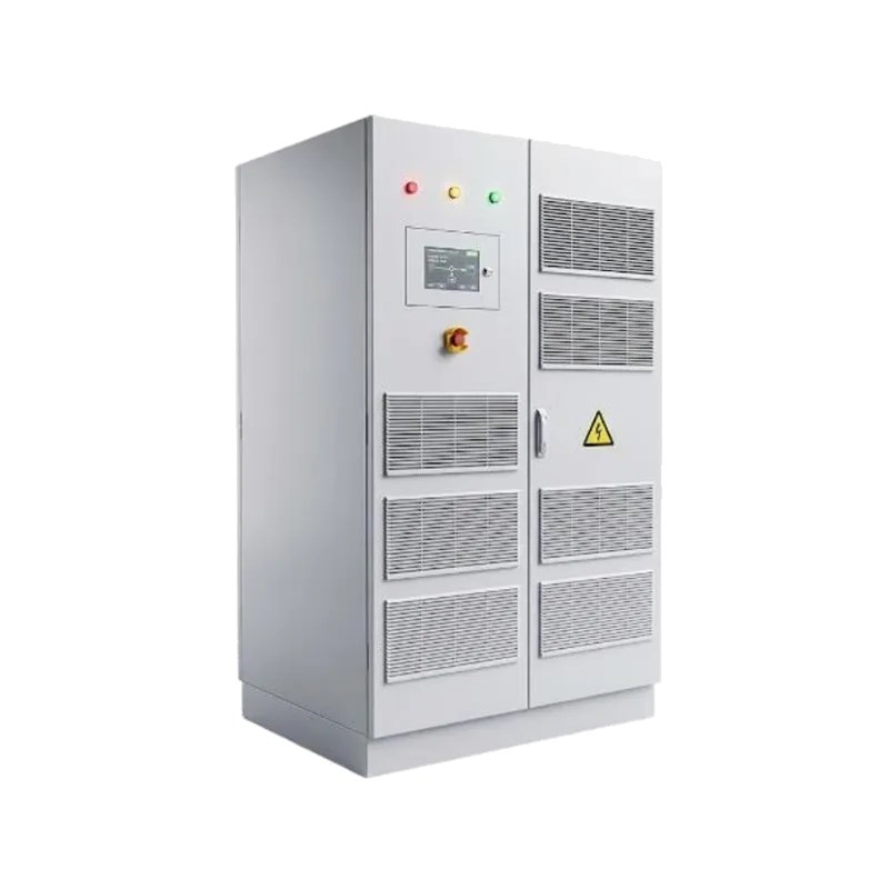
Series PV-Storage All-in-One
- Rated power (grid-tied)375/500kVA
- PV input120kW × 3/4
- Charging efficiency>99.3%
- Active switching0ms
- Protection ratingIP54 / IP20
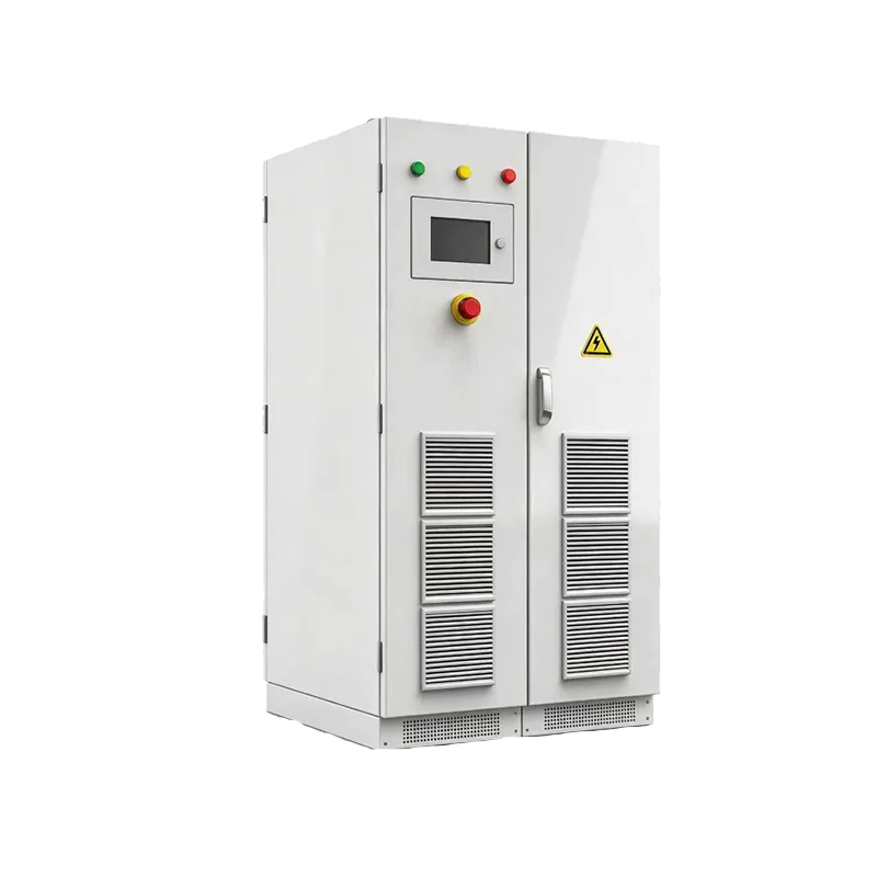
PV-Storage All-in-One
- Rated power (grid-tied)250kVA
- Max output (off-grid)275kW
- Max battery current200A × 2
- PV power60kW × 2
- Protection ratingIP54 / IP20
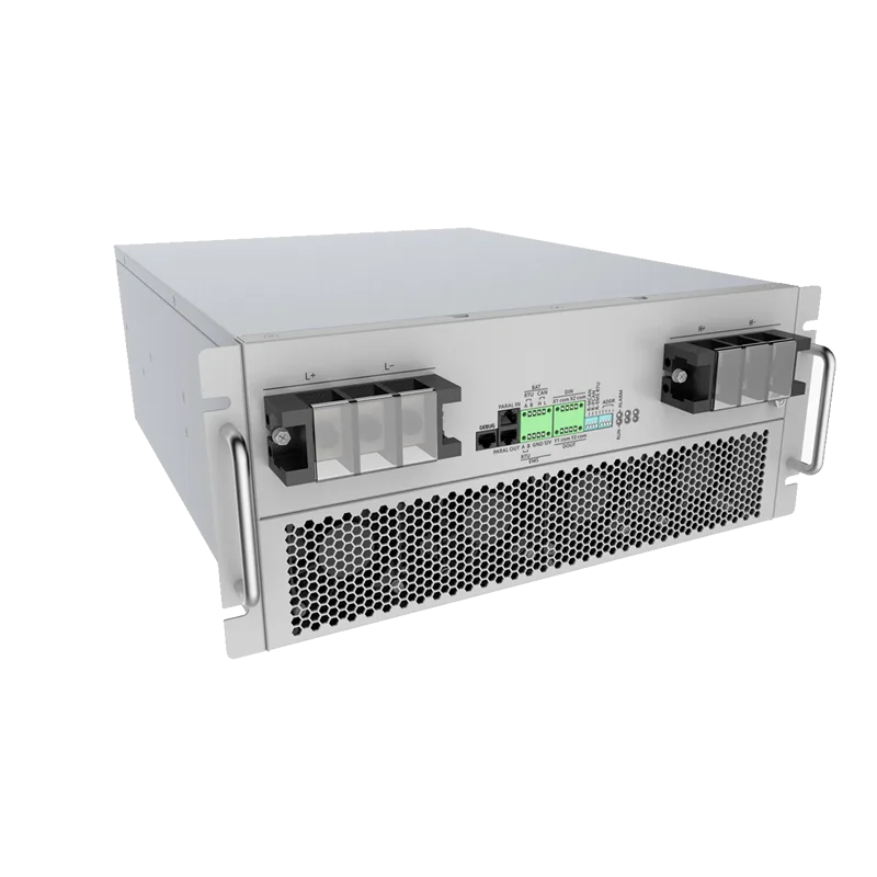
DC Controller
- Rated power210kW
- Input voltage range600-1000V
- Max input current220A
- Peak efficiency99.2%
- Parallel operation6 units
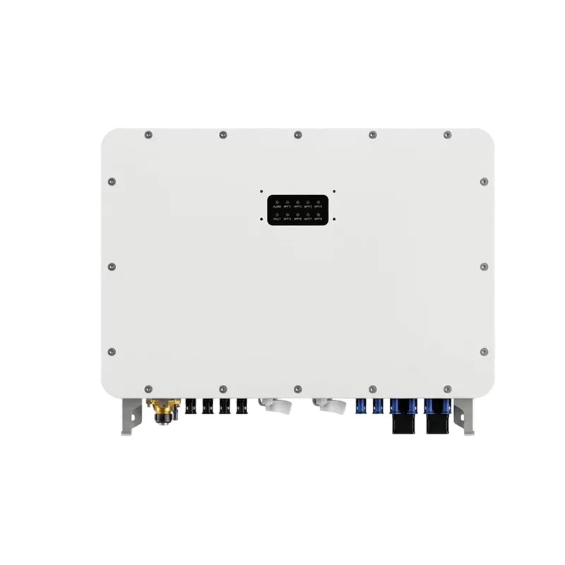
PV MPPT Controller
- Rated power200/150kW
- MPPT voltage range200-900V
- Peak efficiency99.26%
- Protection ratingIP65
- InstallationWall
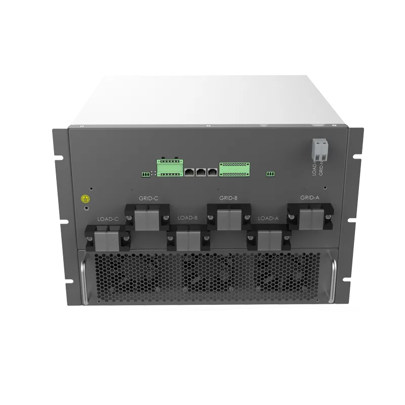
Static Transfer Module
- Rated capacity200/400/600kW
- Max AC current330/660/1000A
- Transfer time<20ms
- Bidirectional detectionBidirectional
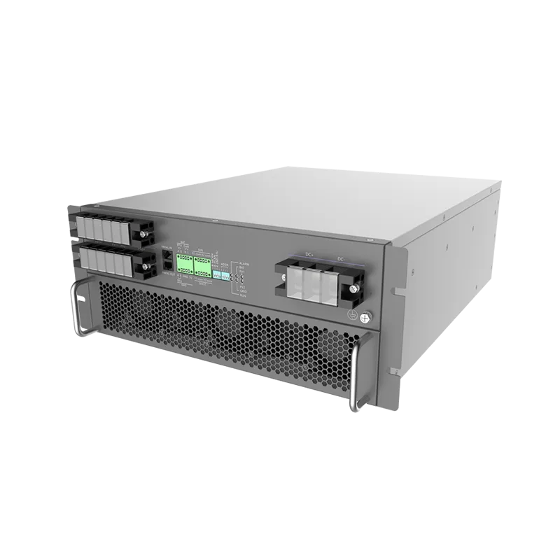
DC-DC Converter Module
- Rated power120/60kW
- Charging efficiency>99.3%
- Parallel operationSupported
The table above shows typical configurations. Actual selection requires the site single-line diagram, load curves and measured data at the interconnection point; VGID POWER can issue a complete selection report based on these.
Four Key Autonomous Capabilities
These capabilities are not add-on features; they are what distinguishes a distributed microgrid from "a pile of networked equipment". To judge whether a solution truly has distributed capability, check whether these four hold up independently.
Fault isolation
When a single node fails, that node's protection device trips to isolate it, and the station-level EMS redistributes power among the remaining nodes so supply is not interrupted. This requires each node's protection settings to be coordinated independently rather than sharing one set.
Layered power dispatch
Critical loads are supported locally by storage first, secondary loads are shed during peak periods, and PV is used entirely on site first, with only the surplus exported. This order must be defined explicitly; an implicit default will shed the wrong loads at the critical moment.
Local consumption
DC coupling lets PV and batteries exchange directly on the DC side, reducing one power conversion stage; station-level dispatch lets each node's surplus energy first supply nodes on the same network segment that are short of power, rather than sending it all back to the grid. This is where most of the benefit of a multi-node system comes from.
Off-grid self-healing
After a grid outage, the station-level EMS drives each node's transfer device to switch to off-grid operation once the loss of supply is detected, the storage establishes the voltage and frequency reference, and loads are then restored in a preset priority order. The restoration sequence depends directly on whether each node has off-grid output capability, which must be confirmed at the design stage.
Dispatch, Metering and Communication
Eighty percent of the O&M experience in a multi-node system depends on how well this layer is done. It does not change the hardware selection, but it determines whether on-site staff face clear data or a pile of alarms every day.
-
Scope of responsibility of the station-level EMS
The station-level EMS handles power flow control at the interconnection point, power allocation among nodes, execution of peak-shaving strategies and generation of external settlement data. Equipment-level MPPT tracking and current-loop control belong to the node layer; the station level should not and need not duplicate them. If this boundary is not drawn clearly, the system will become unstable as two sets of logic compete for control.
-
Metering and settlement
In multi-owner scenarios, it is recommended to meter independently at each node's interconnection point, with the station level only aggregating rather than calculating on behalf of the nodes. This way, even if the parties' contract terms differ, settlement data can still be traced back to a specific node.
-
Communication architecture
Nodes and the station level communicate via RS485 or Ethernet, reporting upward level by level; the station level connects externally to the monitoring platform via 4G or wired links. VGID POWER equipment generally supports RS485/CAN and 4G, so on-site networking is not a bottleneck. One caveat: communication carries only monitoring and strategy delivery and must not be used as a protection channel — protection must be performed independently by hardware protection devices.
-
Authority management for off-grid and grid-tied operation
Off-grid switching affects personnel safety, so authority must be tightly controlled. Switching commands should only be accepted from hard contacts or authenticated communication from the station-level EMS, and a local panel should be provided as an emergency bypass. Avoid allowing commands from any source to trigger switching.
Typical Application Scenarios
Multi-node microgrid in an industrial park
The park contains PV and storage owned by multiple parties and must prioritize self-consumption given the limited interconnection point capacity. The approach is to divide nodes by transformer zone, let each node run independently, and have the station-level EMS handle surplus power sharing. A common practice in parks is to split rooftop PV, storage and charging piles into three to five nodes rather than feeding everything into one station building.
Rooftop PV with storage for commercial and industrial users
The rooftop PV output curve and the load curve do not match in time: output peaks at noon, while some daytime periods also have high consumption; adding storage shifts the midday surplus to the evening peak. The node is usually located below the roof, with capacity configured according to the number of inverters and communication via RS485 to the park aggregation point.
Charging stations coordinated with PV and storage
Charging loads are concentrated in specific periods, and connecting them directly tends to raise the transformer peak. Connecting the charging piles behind the PV-storage node lets the station-level EMS allocate PV and battery output according to charging demand, prioritizing charging during valley periods to reduce demand charges while preventing the charging surge from affecting other loads.
Plant microgrid with multiple complementary energy sources
PV, storage, diesel generators and adjustable loads (such as refrigeration, air compressors and hydrogen production pre-treatment) coexist. The key in such scenarios is not stacking equipment but determining who supplies power under what conditions. The diesel generator starts only when battery SOC falls below the threshold or the load exceeds the PCS capability, and stays on standby the rest of the time.
Data center backup power
For scenarios sensitive to transfer time, the node must have genuine off-grid output capability, not a combination of a grid-tied unit plus an STS. The design should size the battery according to the actual IT load in use rather than installed capacity, and confirm the scope of supply to be maintained during upstream grid maintenance.
Rural distribution area PV-storage pilot
During the day, PV export raises the voltage at the end of the feeder; in the evening the load drops and PV output drops with it, making voltage limit violations likely. Such pilots typically use small wall-mounted models distributed downstream of the distribution transformer, relying on node-level voltage control to limit export rather than on large equipment in a station building.
Overall zero-carbon park solution
When a park applies for zero-carbon or green power certification, the metering basis must match the certification rules. The difficulty in such projects is usually not the equipment but the data: the self-consumption ratio in green power trading, the ownership of surplus power fed to the grid, and green certificate coverage must be determined at the node division stage, otherwise they cannot be traced later.
Distributed expansion of existing station buildings
There is an existing station building and interconnection capacity, and the goal is to add PV and storage without applying for new capacity. The approach is to place the new equipment at locations near the load centers, using the existing interconnection point capacity as a unified constraint. This requires the existing equipment's EMS to support receiving external power commands; otherwise the new nodes can only operate independently.
Design and Implementation Points
-
① Divide nodes first, then select equipment
Node division is based on transformer zones, ownership boundaries and interconnection point locations, not equipment models. First establish "who is where, connected to what, and whose it is", and only then does equipment selection have constraints. Doing it the other way around often results in buying the right equipment that cannot be connected to the grid.
-
② Calculate each node's capacity independently
Sufficient total station capacity does not mean every node has enough. A node's capacity depends on the PV output, load curve and available interconnection point capacity within that node, and the three must match. A common mistake is sizing the battery according to the whole site's peak load, leaving batteries at remote nodes idle for long periods.
-
③ Define the off-grid supply scope clearly
List item by item the equipment that must remain powered during an outage, and confirm each item's starting current. The storage must handle the starting surge of these loads on its own; total rated power cannot be used as a substitute. VGID POWER models generally support 1.1× continuous / 1.25× short-time overload (SP60HCG2 up to 150%), but high-power motors still need separate calculation.
-
④ Set protection settings node by node
Fault current levels differ across nodes in a multi-node system, so applying one set of settings across the whole site will inevitably cause problems. Overcurrent, instantaneous and ground protection settings and time delays must be calculated separately according to each node's equivalent impedance and coordinated with the upstream/downstream grading margins. Grid-tied and off-grid protection criteria differ and must be set separately.
-
⑤ Keep only one reference source when paralleling multiple units
When multiple grid-forming units are paralleled, one must be designated as the master to establish the voltage and frequency reference, with the others following as slaves. Two units establishing a reference simultaneously will cause frequency fighting and circulating currents. VGID POWER SP250HAG2T and SP375/500HAG2 both support three-unit paralleling; the master assignment and switching logic must be specified during configuration.
-
⑥ Choose the right environmental and protection ratings
Outdoor or semi-outdoor: wall-mounted models use IP65 (SP135HAPSS), all-in-one cabinets use IP54 (SP250HAG2T, SP375/500HAG2). In high-temperature areas, note derating — products operating above 45℃ will reduce output according to the curve, and high altitudes (above 2000m) also require derating. If these two points are overlooked, problems are most likely to appear during the summer peak.
Project Gallery







Frequently Asked Questions
How do I choose between a distributed microgrid and a single-point microgrid?
Look at two conditions: whether the nodes are dispersed and under different ownership, and whether the interconnection point capacity is tight. If the resources are concentrated near one station building under single ownership, a single-point solution is simpler and more economical; if the resources are spread across multiple locations with different owners, or the interconnection point capacity is already near its limit, the case for a distributed solution emerges. Hybrid forms also exist — a single-point main body with local nodes.
How much PV and storage can one node carry?
It depends on the combination of equipment within the node. VGID POWER's product line covers 30kVA to 750kVA, from a single wall-mounted hybrid inverter with one battery bank up to a 375/500kVA all-in-one unit with multiple PV inputs. What can actually be connected is mainly limited by three things: the number of PV input channels and the power per channel are limited by the inverter, battery current is limited jointly by the PCS and the cable cross-section, and the interconnection point capacity. The first two depend on the model specifications; the third requires on-site measurement.
What happens if communication between nodes is lost?
Each node should be able to maintain operation independently; this is a basic requirement of a distributed solution. When communication is lost, the node continues operating according to the last power command received, with the local controller taking over, rather than tripping and shutting down. Note that losing communication in off-grid mode has different consequences than in grid-tied mode: when grid-tied, the node can obtain a frequency reference from the grid, whereas off-grid it relies entirely on itself, so the local control logic of an off-grid system must be able to perform voltage and frequency regulation independently.
Does a distributed solution cost more than a single-point one?
Equipment costs are usually higher — multiple points and small capacities mean more units and more communication and protection configuration. But total cost of ownership may be lower: distributed local supply reduces cable length and line losses, a smaller fault impact area means lower losses from outages, and capacity expansion proceeds as needed rather than all at once. Whether it is economical depends on the site's expansion frequency and the magnitude of outage losses; a total cost of ownership comparison over a 10-year period is recommended rather than looking only at the initial quote.
Can a single-point system be converted to a distributed one later?
Yes, but the cost is usually higher than designing for distributed operation from the start. Conversion means adding interconnection points and protection configuration, redoing communication and metering, and possibly replacing existing EMS equipment that lacks distributed interfaces. The real problem is this: if node-level metering and communication were not implemented initially, the historical data for each node cannot be reconstructed during the retrofit, making multi-owner settlement difficult. So the key is not whether it can be converted, but whether interfaces and metering points were reserved at the outset.
How long does a project take from contract signing to commissioning?
The main time is not in equipment supply but in design and approvals. A typical schedule: site survey and data collection 2 to 3 weeks, solution design and selection confirmation 2 to 3 weeks, equipment delivery 4 to 8 weeks (all-in-one units and wall-mounted units differ considerably), installation and commissioning 1 to 3 weeks, grid connection acceptance and filing 2 to 6 weeks depending on the local power supply department's procedures. If storage grid-connection testing or fire safety review is involved, additional time is required.
Is your park suitable for a distributed microgrid?
Provide the interconnection point locations, a list of connected distributed resources and load curves, and VGID POWER can complete the node division and preliminary capacity calculation and give comparative recommendations for distributed and single-point solutions.
Get a Distributed Microgrid Solution